Verse

Luke 12:15 - 21 And he said unto them, Take heed, and beware of covetousness: for a man's life consisteth not in the abundance of the things which he possesseth.
Showing posts with label Survival. Show all posts

Friday, 14 August 2026

Complete Micro Hydro Alternative Power Generation System


How to Install a Complete Micro Hydro Alternative Power Generation System for your Home.
Share this DIY article on

This article provides a comprehensive guide on the installation of a 300W off-grid micro hydro system for residential use.The system is designed to utilize a water source with a flow rate of 15-30 gallons per minute and a 150-foot drop from the source to the home.


The installation process involves several steps, including constructing a screen box, connecting the silt catchment barrel, installing the penstock, connecting the surge tank and pressure gauge, building the housing for the micro-hydro turbine, adding the Turgo turbine, wiring the system, and installing other essential electrical components.
 

STEP 1 : BUILDING A SCREEN BOX

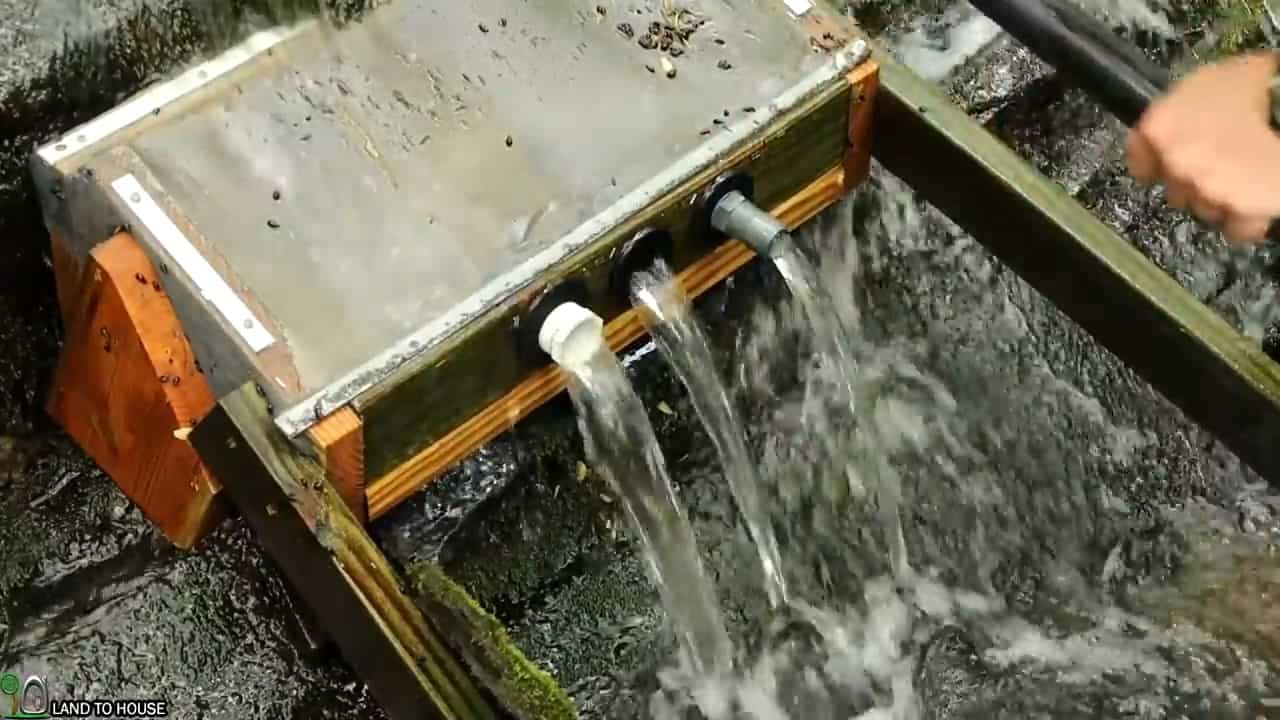
The initial step in setting up a micro hydro system for residential use involves constructing an intake angled screen box to facilitate the flow of water from the source.


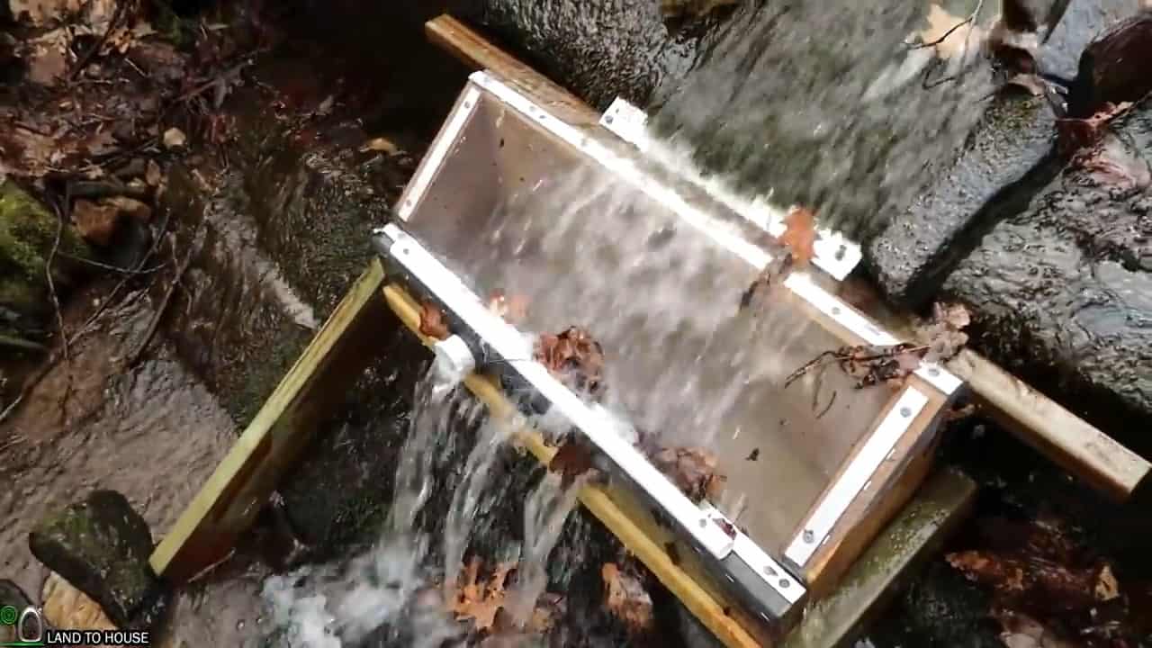
This intake screen box is designed to prevent leaves, sticks, and other debris from clogging the system. The screen box is made of a treated lumber consisting of a 24-inch 2X10, 2X4, and a 2X8 angled piece.
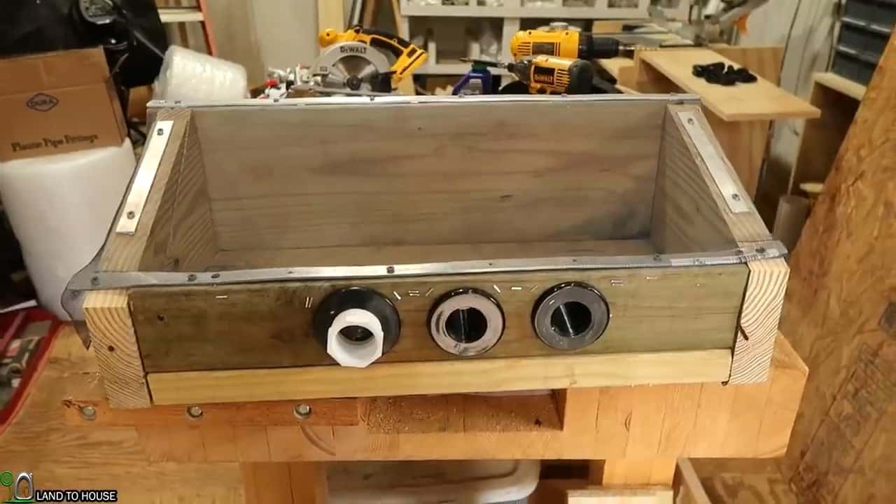
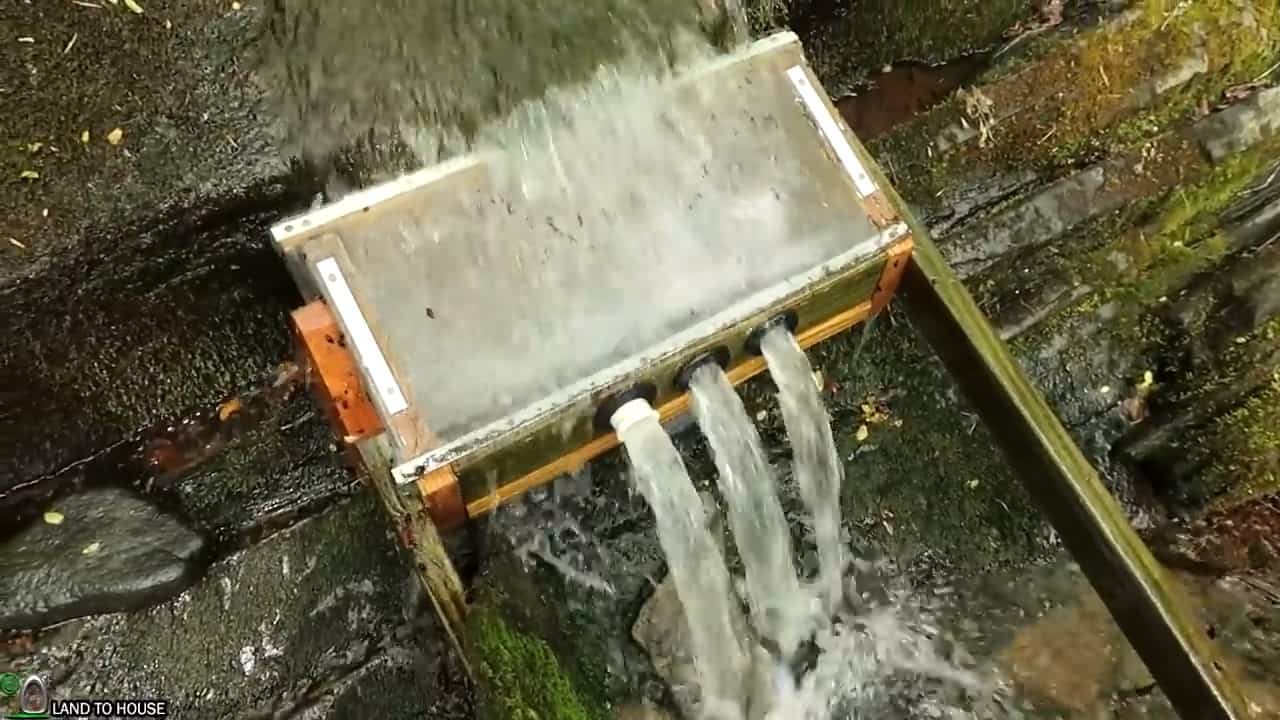
We add 3 one and quarter inch attachment points on the lower side of the box for the HDPE poly pipes.


The box is secured using exterior screws on the outside and inner tubes on the seam to prevent leaks.


Additionally, the box is equipped with three attachment points measuring one and a quarter inches on the lower side for the HDPE poly pipes, which will channel the water to the silt catchment barrel.
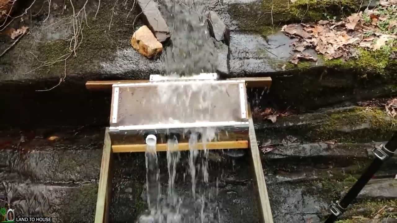
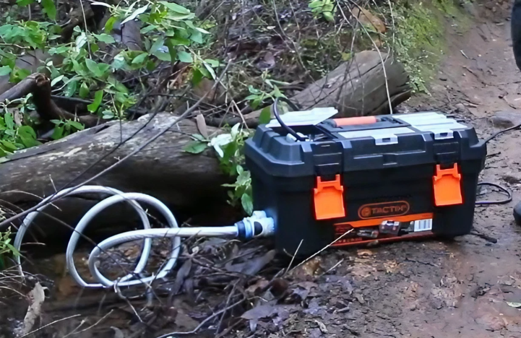
Once completed, the screen box is installed on the creek with the help of three and a half inch concrete anchors and two boards screwed on both sides to provide support.
 

STEP 2 : CONNECTING THE SILT CATCHMENT BARREL

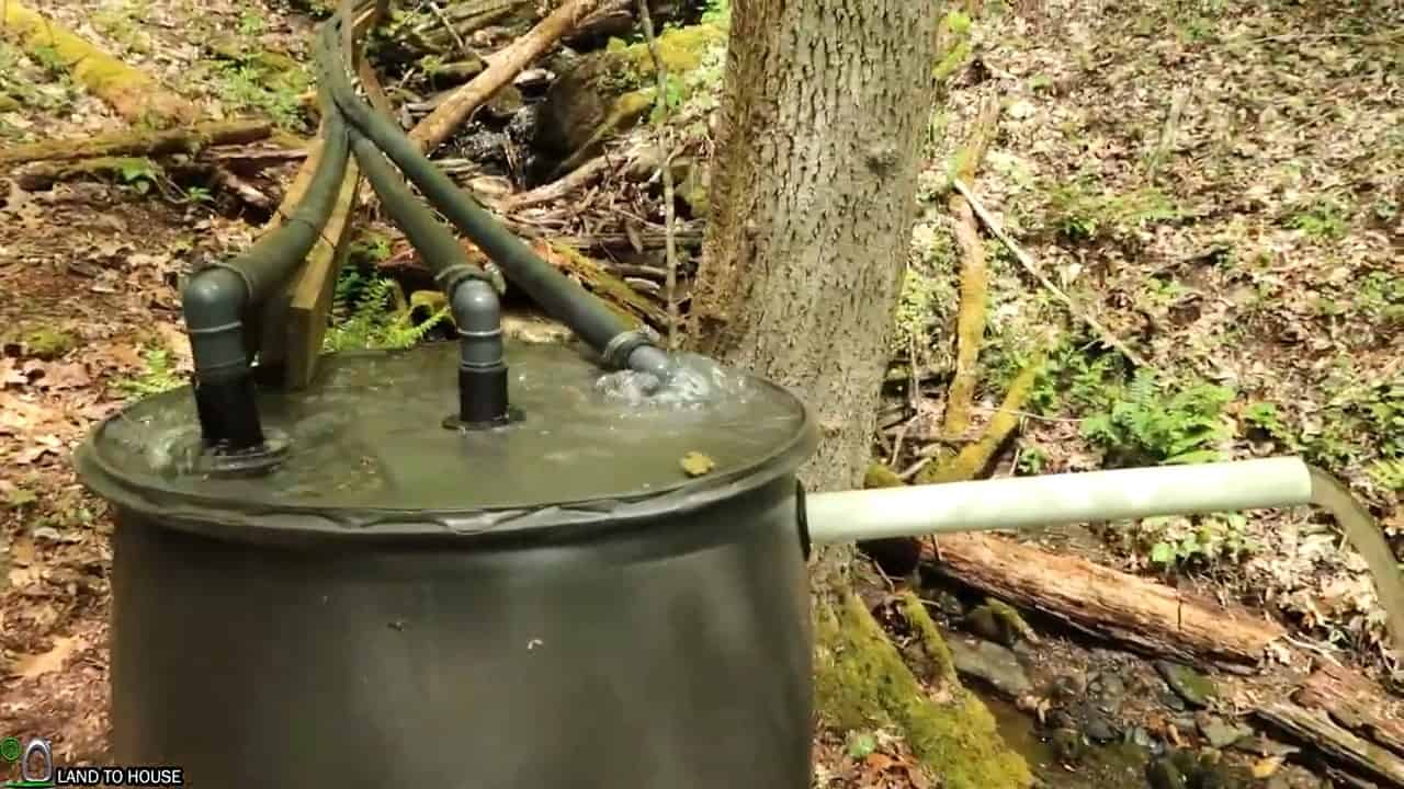
The next step is to connect the outlet poly pipes from the intake angled screen box to a 55-gallon plastic barrel. This barrel is designed to act as a silt catchment and prevent any debris or sediment from entering the micro hydro system.


The three outlet pipes are connected to the top of the barrel using uniseal rubber gaskets, which ensure a tight and leak-proof connection. To facilitate the flow of water to the turbine, a 2-inch pipe is installed midway on the tank for the penstock.
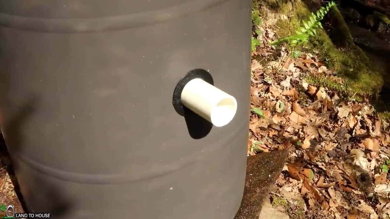
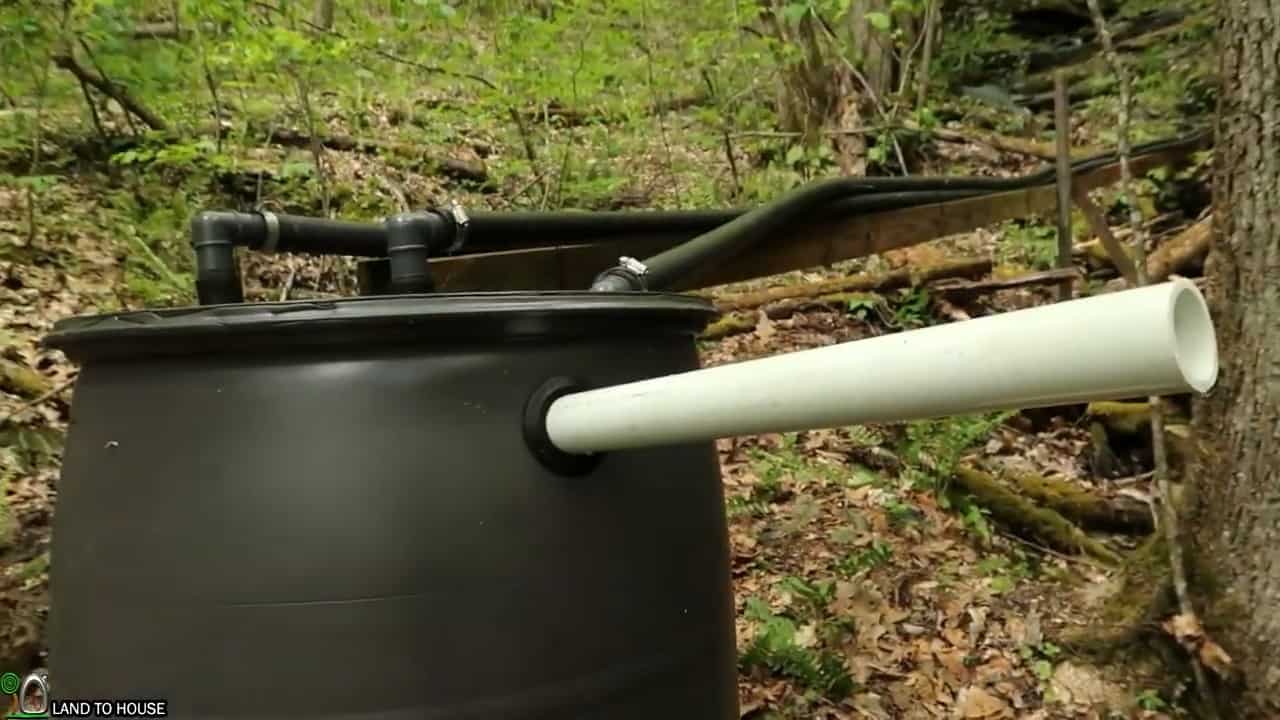
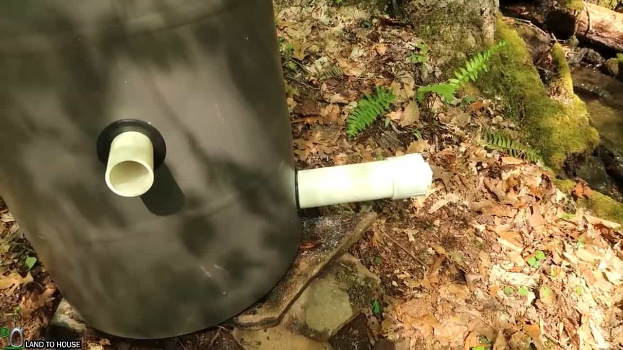
An overflow pipe is also installed near the top of the tank to allow any excess water to flow out of the system, preventing any damage to the micro hydro turbine.


At the bottom of the barrel, a three-inch cleanout pipe is installed to enable easy removal of any silt or debris that may accumulate over time.


This cleanout pipe can be unscrewed for maintenance purposes and re-attached securely to ensure that the system continues to function smoothly.
 

STEP 3 : INSTALLING THE PENSTOKE

The next crucial step in the installation of a micro hydro system involves setting up the penstock, which is responsible for transporting water from the silt catchment barrel to the micro hydro turbine.


In this particular project, a 100PSI 1100ft 2-inch poly pipe has been selected as the penstock. The poly pipe provides the required strength and durability to withstand the high water pressure and ensure a reliable and continuous flow of water to the turbine.


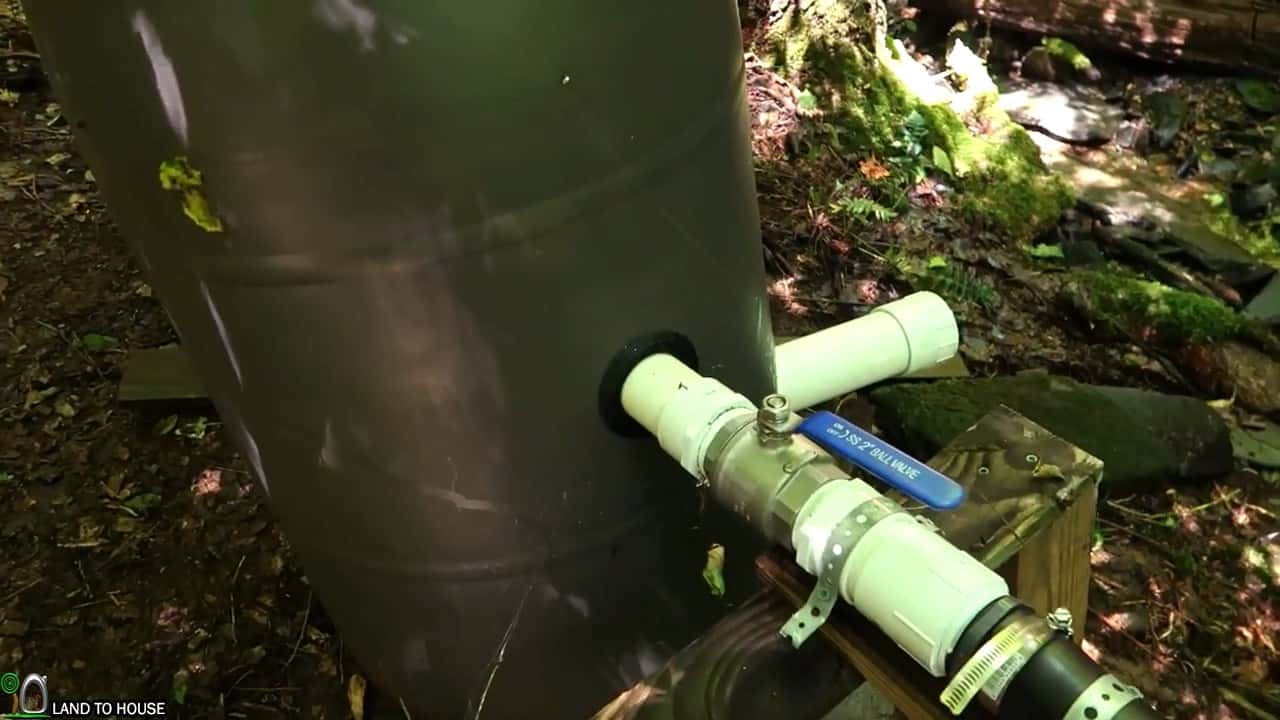
To connect the penstock to the silt catchment barrel, a threaded adapter is glued to the outlet of the barrel. This adapter provides a secure connection and ensures that there is no water leakage from the joint.


A two-inch full port shutoff ball valve is then connected to the adapter, followed by another threaded adapter and a pipe. This setup provides easy control over the water flow to the turbine and allows for quick shut-off during maintenance or repairs.


The penstock poly pipe is attached to this setup using barb fittings with hose clamps. The barb fittings ensure a tight and leak-proof connection, while the hose clamps provide an additional layer of security against any accidental detachment of the penstock pipe.
 

STEP 4 : CONNECTING SURGE TANK AND PRESSURE GAUGE

In the next phase of the installation process, the pressure gauge and surge tank are mounted to the penstock pipe. This step is crucial to ensure that the micro-hydro system runs smoothly and efficiently.


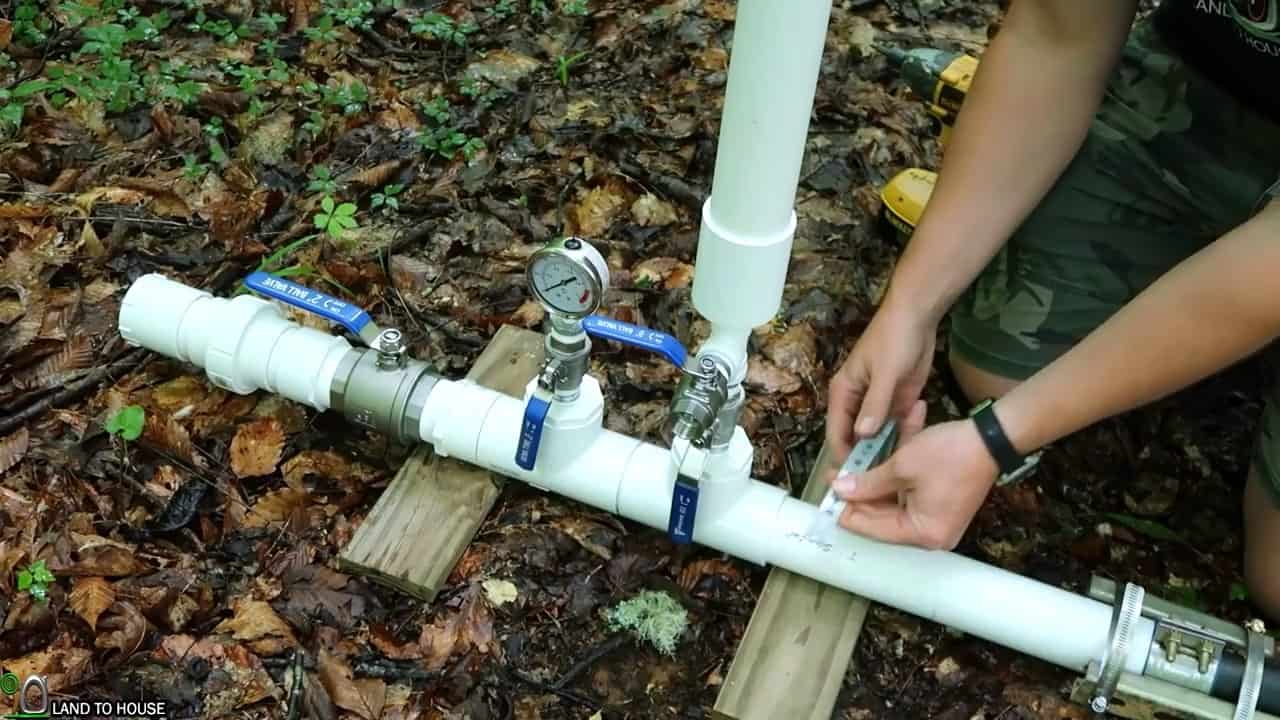
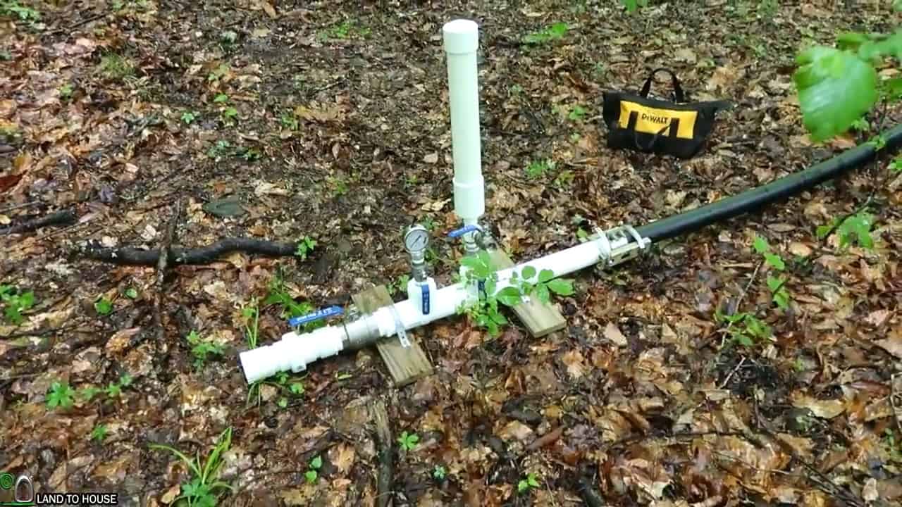
Water flows down from the intake through the poly pipe and into a separate PVC pipe that is equipped with a pressure gauge, surge tank, two-inch closing ball valve, and a union to detach the turbine from the pipe.


The pressure gauge allows for real-time monitoring of the water pressure and flow rate, enabling you to assess the performance of the micro-hydro system.


The surge tank acts as a standpipe that minimizes the impact of water hammer, a phenomenon where sudden changes in water flow can damage the pipes.


The surge tank absorbs any sudden surge or pressure spikes that could occur when the main shut-off valve is abruptly closed, protecting the system from damage and ensuring smooth operation.
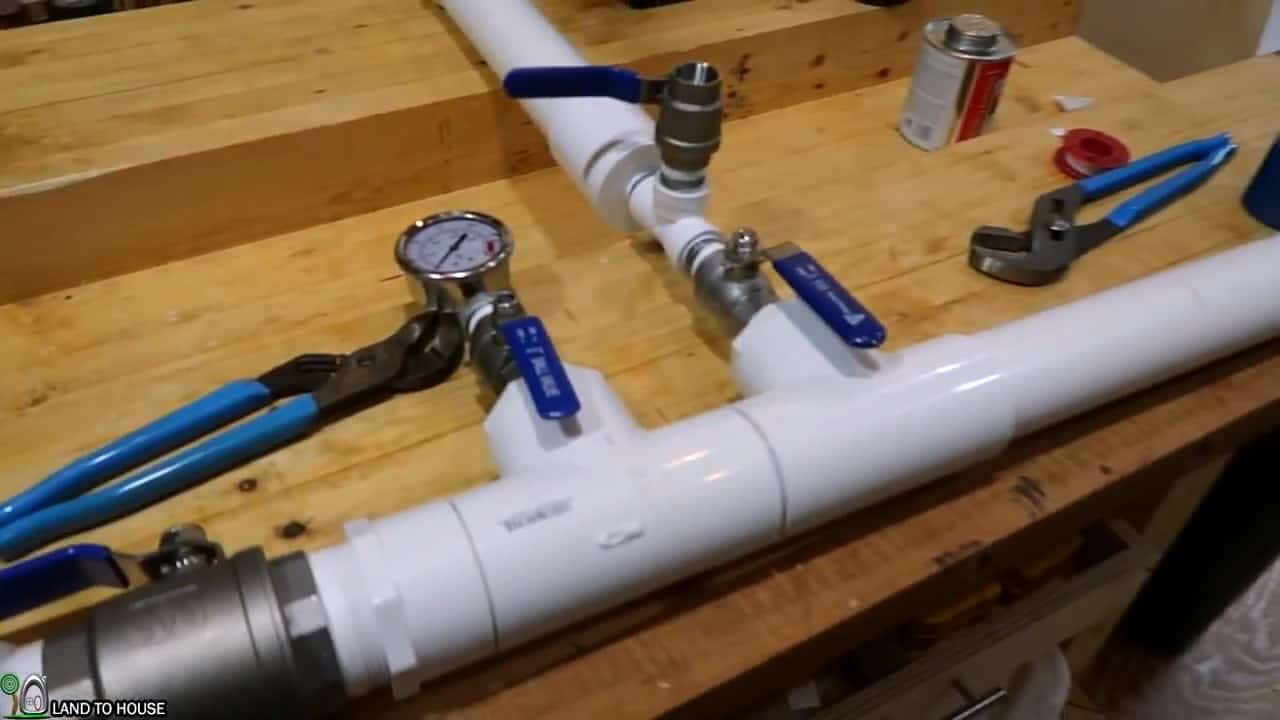
The two-inch poly pipe emerging from the silt catchment barrel is attached to the two-inch PVC surge tank and pressure gauge.


This connection is essential as it creates a cushioning effect that can absorb some of the surge when the main shut-off valve is abruptly shut.
 

STEP 5 : MICRO HYDRO TURBINE HOUSING

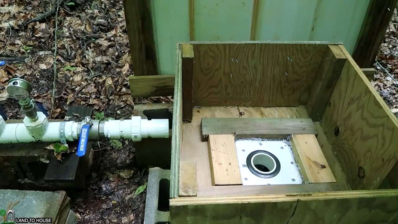
The subsequent step involves constructing a housing for the micro-hydro turbine, which should have a lid that opens up and a drain field pipe that goes out back to the creek.


This housing will be made of three-quarter-inch plywood that is 2 feet wide and 2 feet long and one foot tall, and it will be designed to fit the turbine in the center.


The turbine will be supported by 2×4 scrap wood and a bucket lid piece, ensuring that it is stable and secure. The exit pipe will be 3 inches in diameter and will come out of the housing, going down through the middle to prevent water from accumulating underneath the turbine.
 

STEP 6  : ADDING THE TURGO TURBINE


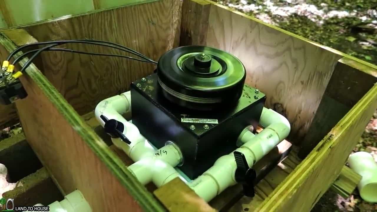
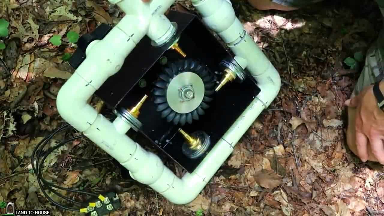
The Micro Hydro Turgo Turbine is a custom-built device designed to match the specific head pressure and flow rate of the water source.


The device is equipped with three ball valves and four quarter-inch jet nozzles coming out of them. These ball valves are designed to be separately turned off when there is not enough water, thus avoiding damage to the turbine.


The Turgo Turbine is wired up to be a three-phase system. The water coming out of the penstock hits jet nozzles that turn the Pelton wheel, which is connected to a 3-phase AC motor.

This setup ensures maximum efficiency in the energy conversion process.
 

STEP 7  : WIRING THE SYSTEM

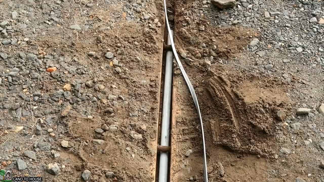
To connect the turbine to our house, we use a 10/3 underground feeder wire, which is specifically designed to handle the electrical load generated by the micro-hydro turbine.


To ensure the wire is protected from damage and the elements, it is enclosed in a one-inch conduit pipe, which acts as a protective shield.


The conduit pipe is first assembled using adhesive glue to ensure it is tightly sealed and secure. To easily pull the wire through the conduit, a vacuum is used to create suction that pulls a string through the entire length of the conduit. The wire is then tied to the string and pulled through the conduit with ease.


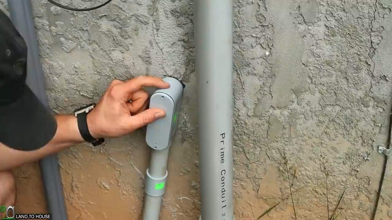
Once the wire is through the conduit, it is routed into the house through a PVC conduit body, which is a specially designed connector that provides a secure and waterproof seal between the conduit and the house wiring.
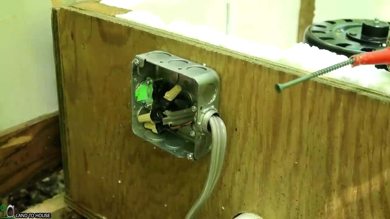
Next, we proceed to install a junction box on the housing of the turbine. This junction box connects the output wires of the three-phase turbine to the 10/3 UG feeder wires that run from the house. Inside the house, we connect a rectifier to the three legs of the three-phase coming from the turbine.


This is an important step as it converts the AC generated by the turbine into DC power that can be used by the home’s electrical system.
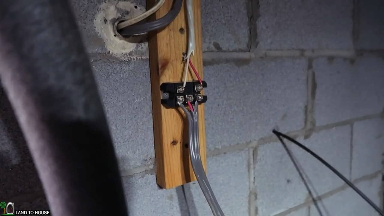
 

STEP 8 :  INSTALLING OTHER ELECTRICAL COMPONENTS

In order to transform the generated DC power from the micro-hydro system into useable AC power for household appliances, several electrical devices need to be installed.


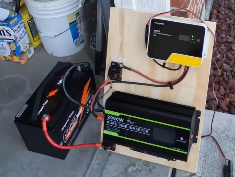
These include the MPPT (Maximum Power Point Tracking) Charge Controller, Grid Tie limiter Inverter, breaker box, disconnect switches, and batteries. To organize and secure these components, they are mounted on a 2 X 2 foot, three-inch plywood board.


To ensure proper heat dissipation and prevent damage to the electrical components, it is important to take measures to mitigate excess heat.


For this reason, a piece of sheet metal can be placed over the plywood board to act as a heat sink. This will help to regulate the temperature of the electrical components and ensure optimal performance.
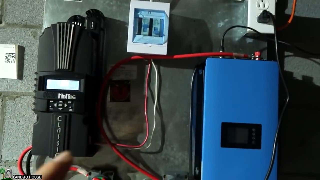
After the three-phase output wires from the rectifier are connected to the breaker box, the red wire is then connected from the breaker box to the positive terminal of the MPPT (Maximum Power Point Tracking) charge controller.


The MPPT charge controller is an essential component of the micro-hydro system, as it optimizes the power output of the turbine by ensuring that it operates at the maximum power point (MPP). This helps to maximize the efficiency of the system.


The negative white wire from the rectifier is directly connected to the negative terminal of the MPPT charge controller.


This completes the circuit between the turbine and the charge controller, which regulates the flow of current from the turbine to the batteries.
 

STEP 8 :  CONNECTING THE BATTERIES AND COMPLETING THE WIRING

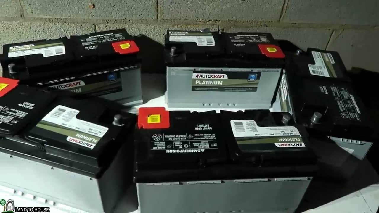
In this step, we will connect the five 12V AGM batteries in series using four gauge cables. This will increase the voltage to 60V, which is necessary for proper functioning of the system.


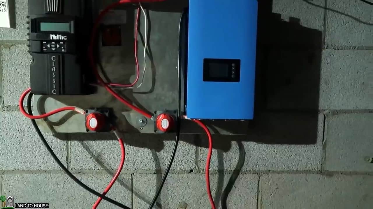
Once the batteries are properly connected, we will connect the positive terminals to the MPPT charge controller and the grid tie limiter inverter using DC switches.


These switches will allow us to isolate and disconnect the components individually for maintenance purposes.


After connecting the positives, we will then connect the negatives of the batteries to the negatives of both the charge controller and inverter respectively.


This will complete the DC circuit of the system. The MPPT charge controller will monitor the voltage and current of the batteries and regulate the charging process to ensure that the batteries are not overcharged or undercharged.


The grid tie limiter inverter will convert the DC power from the batteries to AC power that can be used in our home. The inverter is further connected to the receptacle from where it goes straight to the main supply.


We will also install DC and AC disconnect switches for safety purposes. These switches will allow us to easily disconnect the system in case of an emergency or maintenance requirements.

Image Credits : Land to House

Build a Simple Backyard Bio Sand Water Filtration System


How to build a Simple Backyard Bio Sand Water Filtration System from easily available materials .

Share this DIY article on

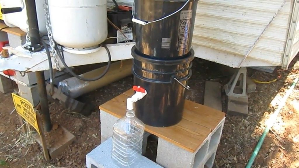
This project provides detailed instructions for constructing an affordable bio-sand water filtration system that is capable of removing pollutants from various sources such as streams, lakes, gutters, and well water.


Bio sand filters are highly effective in removing harmful microorganisms like parasites, bacteria, and protozoa viruses, as well as fine sediments from water sources.


FOUR STAGES OF PURIFICATION

The bio-sand water filtration system operates on four stages of purification that work in a sequential manner to remove harmful contaminants from the water.


The first stage, known as the biological zone, involves the growth of bacteria on the surface of the biozone. These bacteria feed on parasites, pathogens, and viruses, effectively eliminating them from the water.


The second stage, mechanical trapping, involves the attraction of sediment to porous rock. The sediment is then filtered out through absorption, which is the third stage.


The electrostatic charge of the sand in the filter attracts small particles and viruses down to the virus level. This effectively removes these harmful particles from the water.


The fourth and final stage is natural death from nutrient depletion. As the bacteria and viruses go through the sand, they eventually run out of nutrients to feed on, and as a result, they die off naturally.


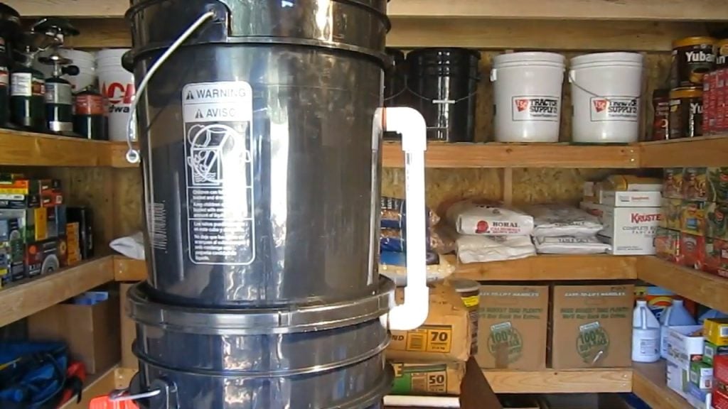
STEP 1  : STACKING THE BUCKETS

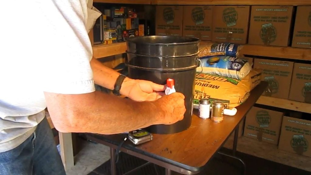
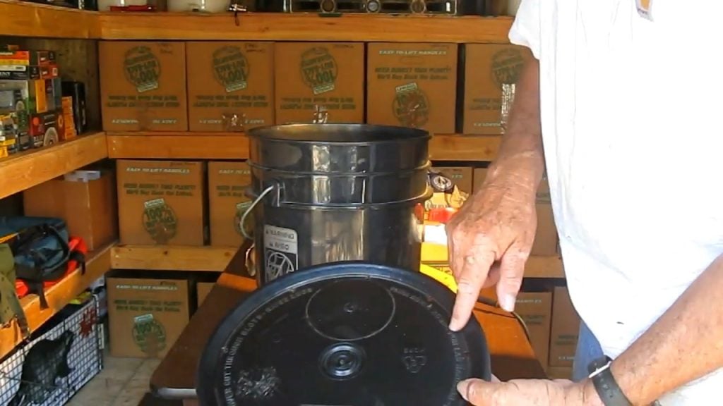
To construct the bio-sand water filtration system, you will need two five-gallon buckets. These buckets are typically used for storing food and are available in black color.


These buckets are preferred over opaque ones as they do not promote the growth of algae. The buckets are stacked one on top of the other, with the top bucket serving as the water storage container and the bottom one serving as the filter.


The top bucket is where the polluted water is initially stored, and from where it is eventually filtered through the bio-sand layer present in the bottom bucket.


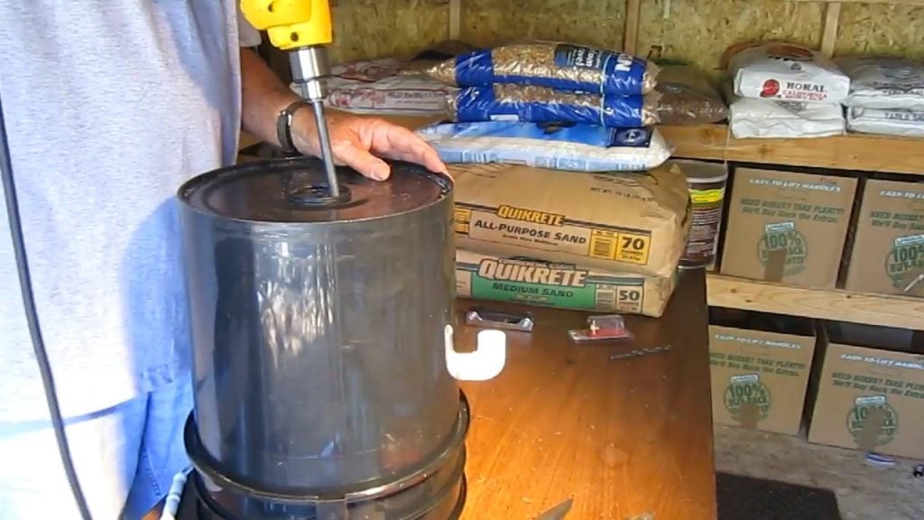
STEP 2   : MAKING HOLES ON THE LID AND AT THE BOTTOM

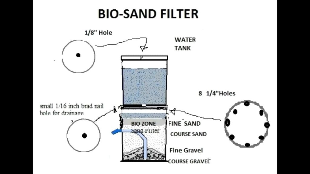
The top bucket of the bio-sand water filtration system features an eighth-inch hole on its lid. This hole serves an essential function of allowing water to flow freely without creating a vacuum.


Without this hole, the pressure inside the bucket would increase, hindering the flow of water to the lower bucket. The hole enables a smooth and continuous flow of water through the system.


On the other hand, the bottom bucket has a 16th of an inch hole at its bottom. This hole is strategically placed to allow the water to slowly drip out onto the top of the bottom bucket, where it comes into contact with the bio-sand layer.


STEP 3   :  PROTECTING THE BIOZONE

The bottom bucket of the bio-sand water filtration system has eight one-quarter inch holes along the sides.


These holes serve to disperse the water over the top of the sand layer, allowing it to drip down onto the biozone without disturbing it.


This careful drip pattern ensures that the biozone is not disturbed or destroyed during the filtration process, resulting in effective removal of harmful contaminants.


It takes approximately three weeks to establish the biozone, during which period you need to feed some polluted water containing bacteria to help the biozone develop and grow.


This feeding process allows the bacteria to establish and multiply, ultimately leading to the effective removal of parasites, bacteria, protozoa viruses, and fine sediments from the water.

To ensure proper distribution of bacteria in the bio-sand water filtration system, a large circular ring can be placed in the center of the biofilter.


This ring serves to distribute the bacteria off to the side, ensuring even distribution of bacteria throughout the sand layer.


This even distribution is essential to the functioning of the filtration system, as it relies on bacteria that form on the top of the sand to eat other bacteria such as Giardia and Cryptosporidium.

STEP 4   :  ADDING THE CENTER PIPE


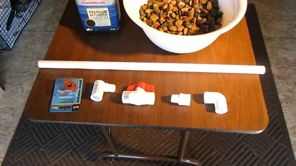
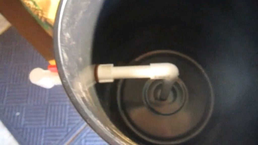
In the bio-sand water filtration system, a pipe is placed at the center of the system to prevent sand from entering the faucet and ultimately contaminating the drinking water.


This pipe is an essential component of the filtration system, as it serves to keep the sand layer separate from the purified water.


Without this pipe, there is a risk that the sand layer could be disturbed, allowing it to enter the faucet and ultimately the drinking water.


STEP 5   :  TWO LAYERS OF SAND

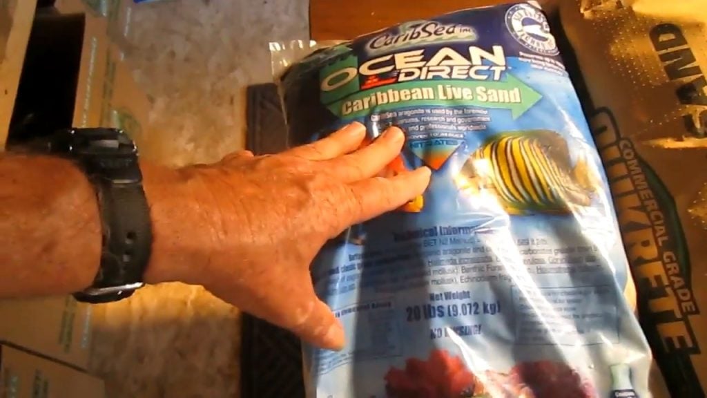
The bio-sand water filtration system comprises two distinct layers of sand. The first layer, which is the biozone, is designed to promote the growth of bacteria, which are responsible for removing harmful contaminants from the water.


This layer comprises a couple of inches of fine sand, which provides an ideal environment for the bacteria to grow and thrive.


Underneath the biozone is a second layer of sand, which serves as a mechanical filter to remove sediment and other bacteria from the water.


This layer comprises a coarser sand, which is selected for its ability to trap and filter out harmful particles from the water.


At the very bottom of the filtration system is a layer of fine pea gravel, which serves as a final layer of filtration before the purified water is collected in the bottom bucket.


This layer is designed to filter out any remaining particles or contaminants that may have passed through the sand layers.


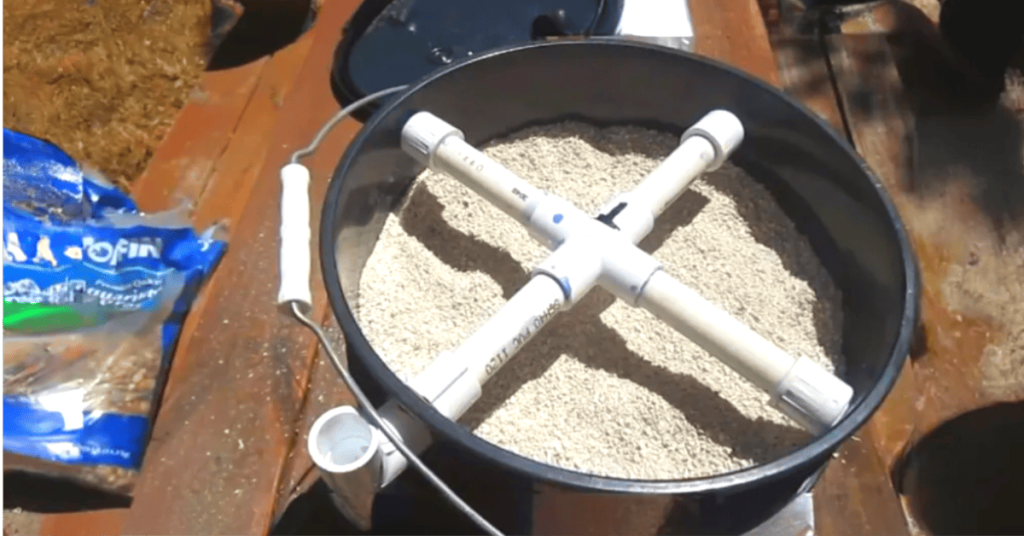
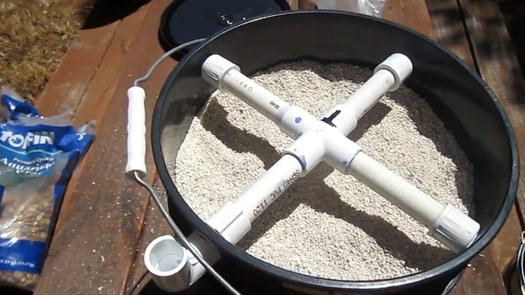
STEP 6  : ADDING A FOUR WAY DISTRIBUTION PIPE

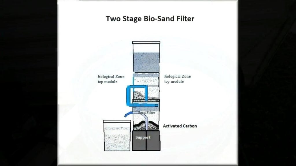
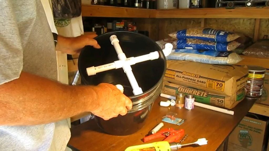
The second stage of the bio-sand water filtration system involves the construction of a 4-way distribution pipe using PVC pipes and a four-way coupler.


This pipe serves to distribute the water evenly over the top of the sand layer, ensuring that the water is not concentrated in one spot and trickling down one side or the center.


To achieve this even distribution of water, holes are cut in the distribution pipe, one towards the end and the other towards the center.


This allows water to flow out of the pipe in multiple directions, resulting in a more uniform distribution of water over the top of the sand layer.

To ensure the bio-sand water filtration system is easy to maintain, a hole is drilled at the bottom of the second bucket, and a quarter-inch brass drain plug is inserted.


This drain plug serves as a convenient method to drain water out of the buckets for storage or flushing purposes.


STEP 7  : STARTING THE SECOND STAGE

The second stage involves the addition of three levels of gravel and three levels of sand. Each layer of gravel is two to three inches thick, and each layer of sand is also two to three inches thick.


On top of the last layer of fine gravel, one inch of activated carbon is added. This carbon layer serves to remove any remaining impurities from the water, resulting in high-quality purified water that is safe for consumption.


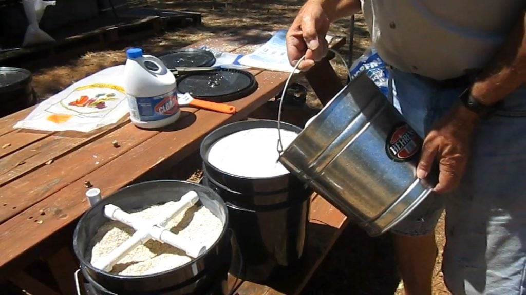
Before adding the activated carbon layer, both filters are treated with chlorinated water and fresh water, and allowed to sit for a few minutes.


This treatment serves to sterilize the filters and ensure that any harmful bacteria or viruses are effectively removed from the system.


Once the second stage filter is complete, it is stacked on top of the first stage filter, ensuring that the entire setup is tightly sealed.

In addition to the filtration system, the bio-sand water filtration system can also use the natural power of the sun to further purify the water.


By letting the purified water sit under the sun, the ultraviolet rays present in sunlight can further purify the water by eliminating any remaining bacteria that might be present.

Friday, 7 August 2026

How to build your own Solar Powered Water Heater from Start to Finish


How to build your own Solar Powered Water Heater from Start to Finish . Step by Step Build Instructions..

Share this DIY article on


As a homeowner, you understand the significance of having a reliable and efficient water heating system. Traditional water heaters, however, can be costly to operate and contribute to your household’s carbon footprint. What if there was a way to harness the abundant energy of the sun to heat your home’s water supply. This DIY project goes over the process of constructing your own solar water heater, designed to capture the sun’s radiant energy and transfer it to your home’s water system.

STEP 1 : Materials Needed


  • Panel Base: Marine plywood, cut to desired size (larger than the glass)
  • Glazing: Glass sheet, cut to desired size
  • Insulation : 2 Layers of Thermal insulation sheet
  • Absorber : Aluminum sheet (0.8 mm thick, same size as plywood)
  • Thin-walled copper tubing (3 rolls of 25 meters each, with small internal diameter)
  • Frame: External decking wood (pressure treated)
  • Insulation: Thermal tape for LED strips
  • Sealant: External silicone sealant
  • Adhesives: Cable ties, hose clamps
  • Paint: Plasticote Matt Black spray paint
  • Fittings: Copper adapters (3x)
  • Hardware: Screws, nails

STEP 2 : Prepare The Base

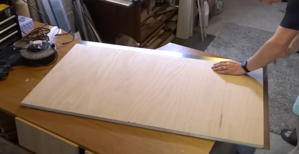
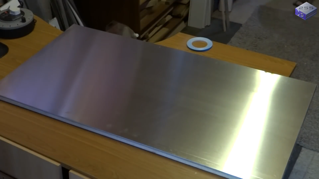
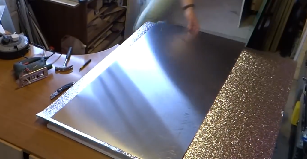
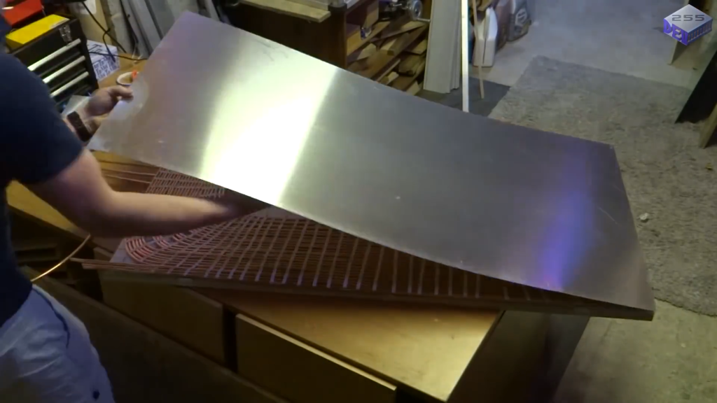
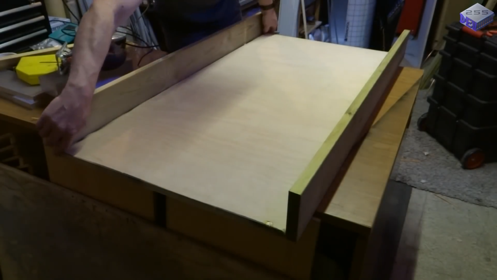
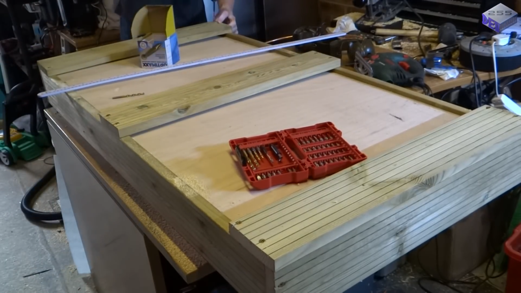
Cut the marine plywood to the desired size for the panel base. This should be larger than the glass sheet to accommodate the frame and allow for adequate insulation.Cut a sheet of 0.8 mm thick aluminum to the same size as the plywood base.

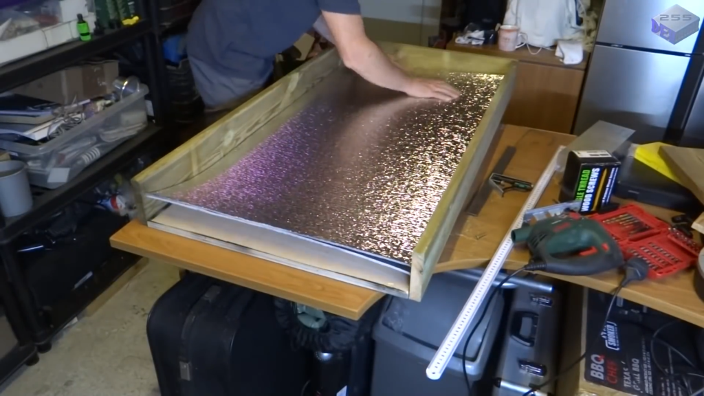
Deburr the edges after cutting. Apply two layers of thermal backing to the plywood to minimize heat loss. Thermal backing acts as an insulating layer between the plywood board and the aluminum sheet with the copper tubing. It helps to minimize heat loss from the back of the solar collector.

STEP 3 : Create the Absorber Surface

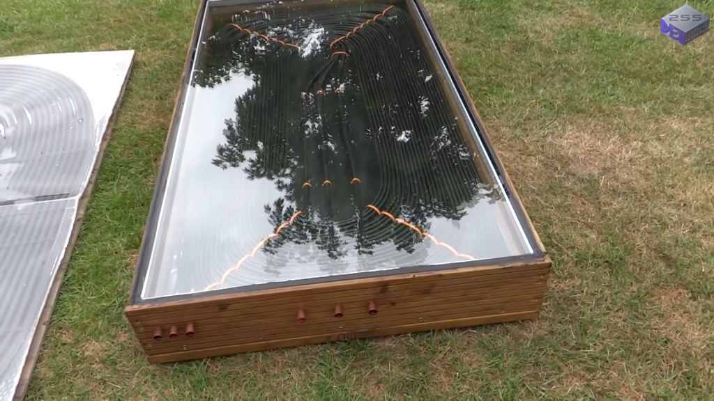
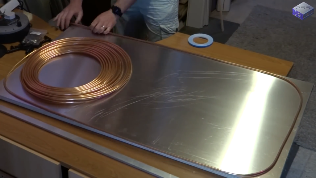
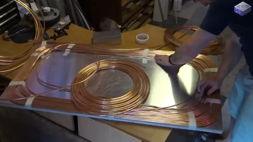
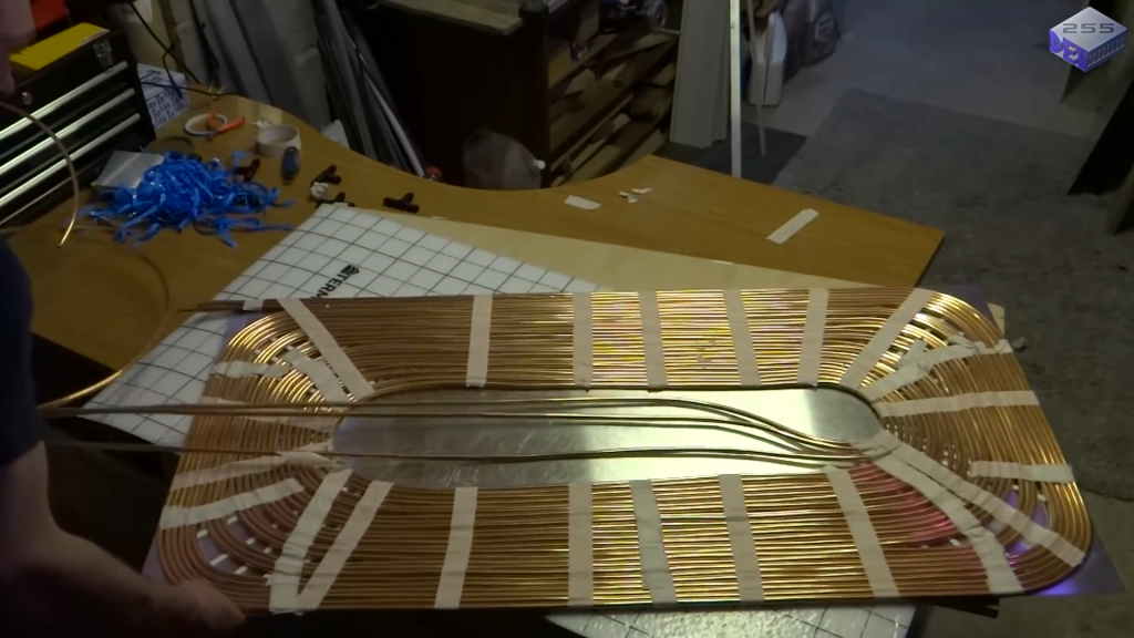
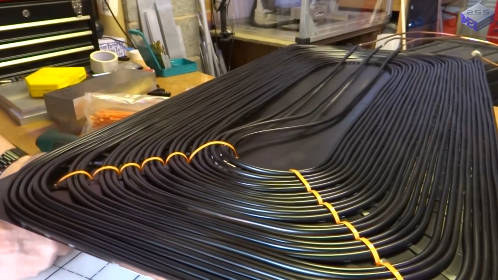
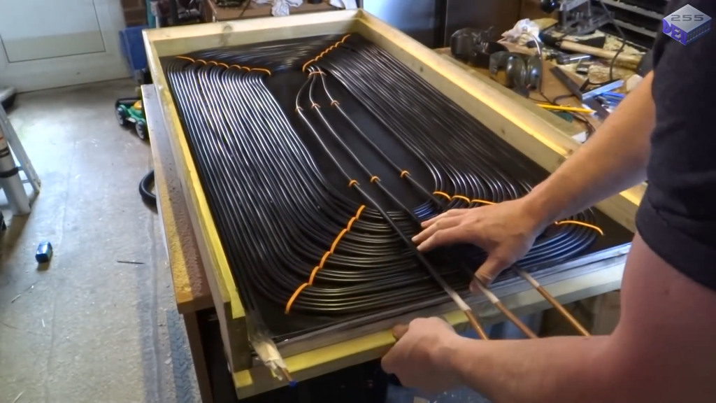
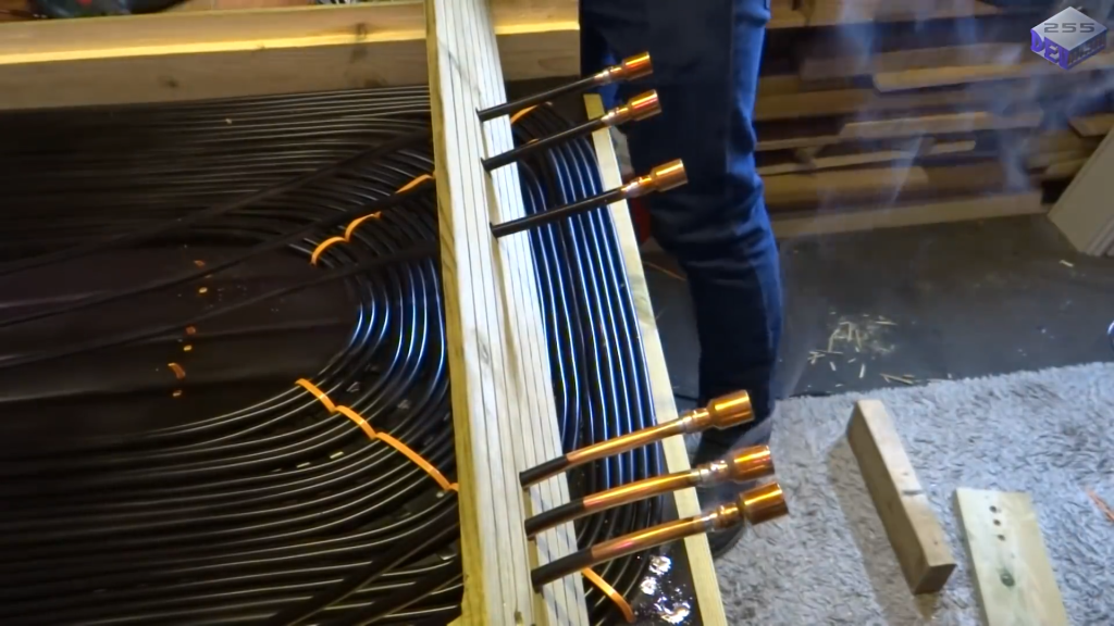
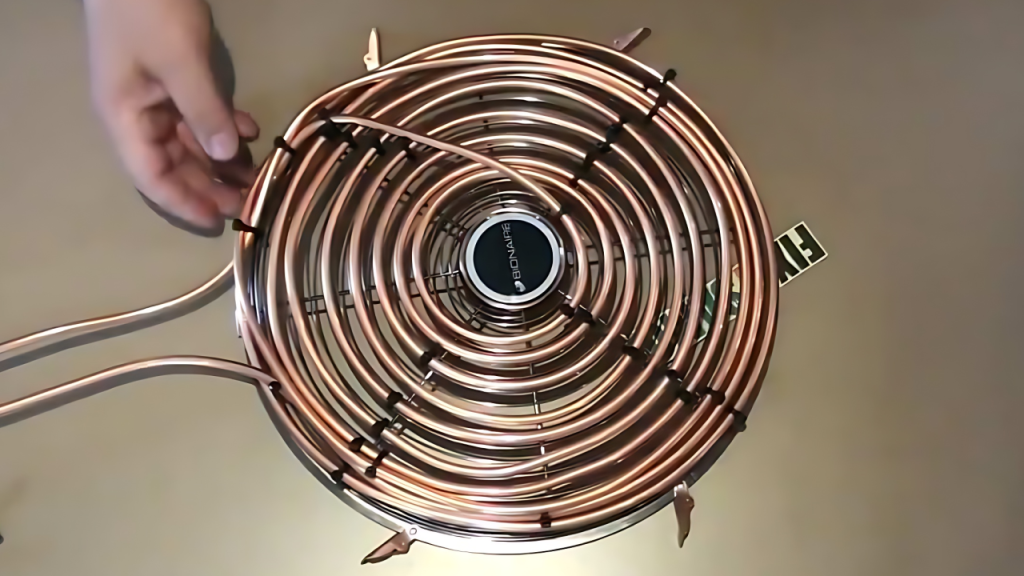
Lay out the copper tubing on the aluminum sheet, creating a series of parallel runs with even spacing. You can adjust the spacing and number of runs based on your desired flow rate and heating capacity. Here we are using three rolls of copper tubing, each measuring 25 meters in length. This totals to 75 meters of copper tubing.

The thin-walled, small-diameter copper tubing provides a greater surface area compared to thicker tubing with a larger internal diameter. This increased surface area allows for faster heat transfer from the sun-heated copper to the water flowing through the tubing.


By maximizing the surface area, the solar pool heater can more efficiently capture the sun’s energy and transfer it to the water. This design choice ensures that the heat is quickly absorbed by the water, rather than remaining in the panel itself.

STEP 4  : Attach Thermal Tape 

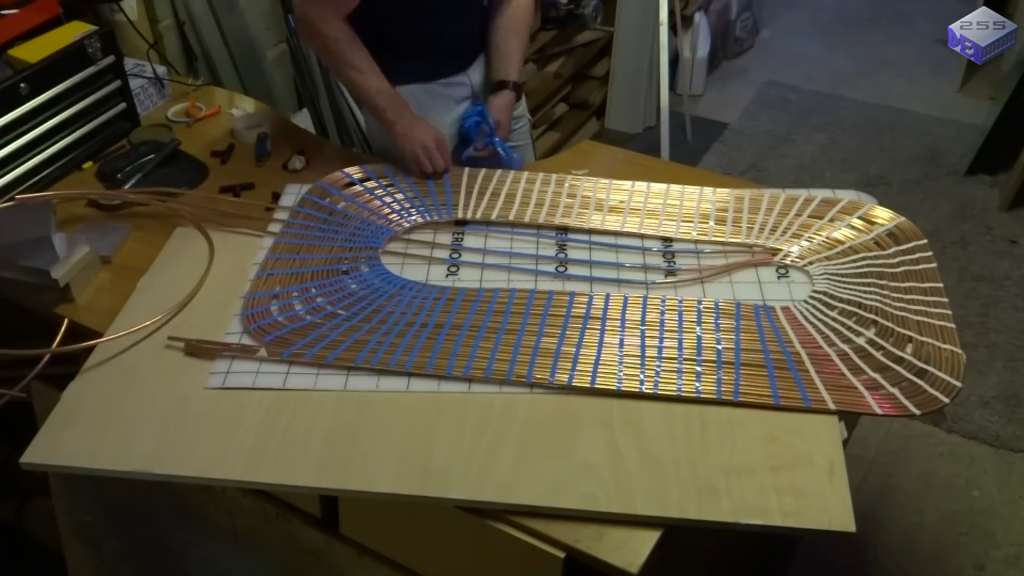
Remove the tubing and aluminum sheet from the plywood base. Apply thermal tape, designed for LED strips, to the back of the aluminum sheet to facilitate heat transfer. Reattach the aluminum sheet and tubing .

By applying thermal tape between the aluminum plate and the copper tubing, the heat is effectively conducted from the aluminum to the copper. The more effectively the heat is transferred from the aluminum plate to the copper tubing, the more quickly and evenly the water flowing through the tubing will be heated.

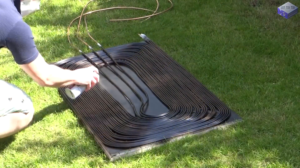
Spray paint the entire surface, including the tubing, with  Matt Black spray paint. Apply multiple coats for optimal heat absorption.

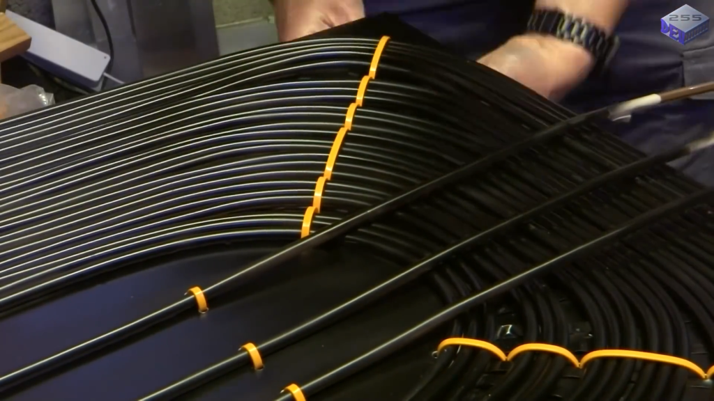
Once the copper tubing is arranged in the desired pattern on the aluminum sheet, cable ties are used to secure the tubing at regular intervals.The thin–walled copper tubing is flexible and can easily bend or move out of position. 

Cable ties hold the tubing firmly in place, ensuring the desired layout is maintained throughout the construction process and during operation.

Step 5: Construct The Frame


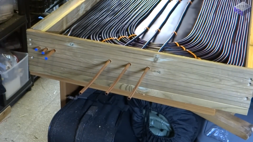
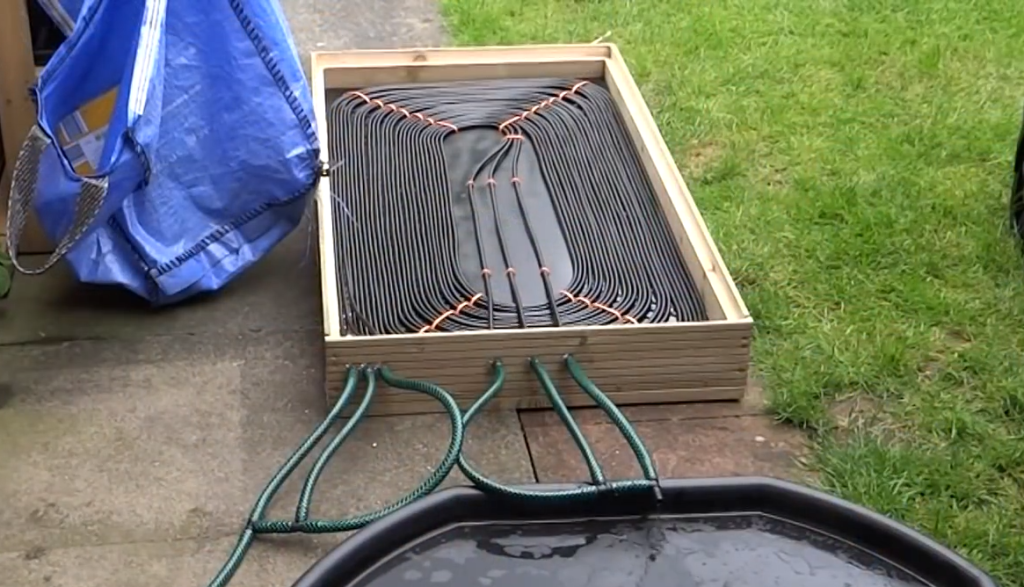
Using the external decking wood, construct a frame that fits around the perimeter of the panel base, ensuring it is square.All the pipe connections are located outside the panel, rather than having any connections inside.


This minimizes the risk of leaks occurring within the sealed unit. If a leak were to develop at a connection point inside the panel, it would be difficult to detect and repair without disassembling the entire unit. Also you can reconfigure the way the pipes are connected, which would be more challenging if the connections were located inside the sealed panel.

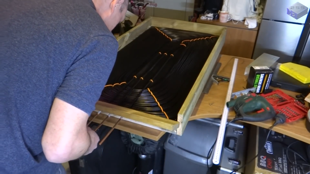
The end piece allows the entire heating element to be slid out of the frame while leaving the glass in place. Here we can access the inside of the panel if needed by simply cutting the seal around the glass at the front and sliding the heating element out, without having to remove the entire glass unit.

Attach braces to the underside of the frame for additional support and stability.These braces are designed to maintain the frame’s structural integrity and prevent it from becoming misaligned or warped.

Step 6: Installing The Pipe Adapters


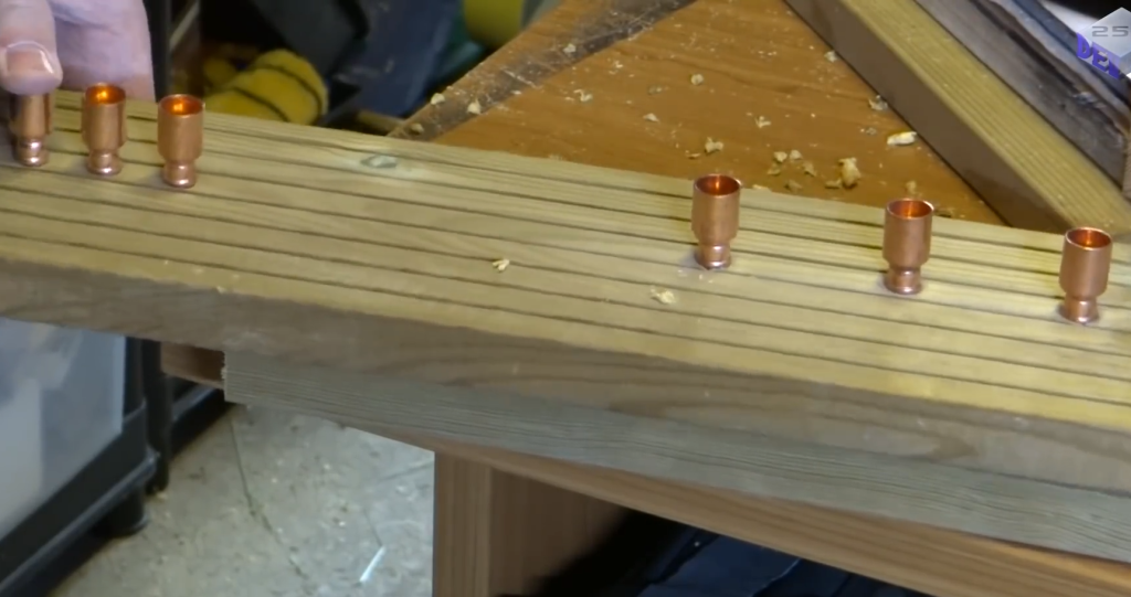
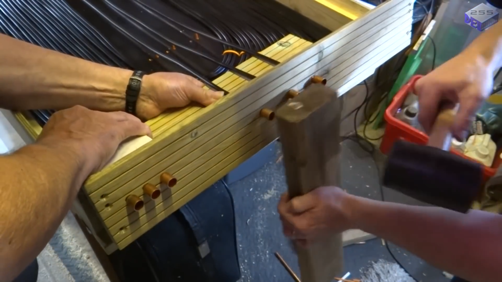
Drill 10.5 mm holes into the frame to fit the pipe adapters snugly. Measure and cut the copper tubing to ensure the adapters sit flush with the frame. 


Clean the tubing ends and solder the adapters in place. Hammer the adapters into the frame.

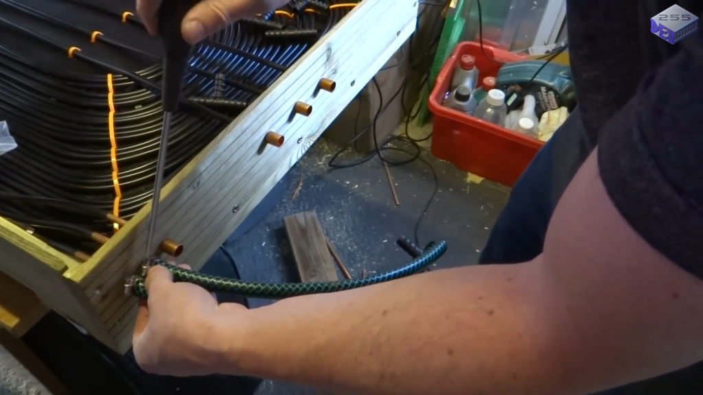
Connect standard hosepipes to the adapters using hose clamps. Configure the pipes in parallel for quick water flow and efficient heat transfer or in series for a more gradual heating process.

Connecting the pipes in parallel allows the water to flow through the system very quickly. In a parallel configuration, the water is divided among the three pipes, reducing the overall resistance and increasing the flow rate. This allows the heat energy collected by the panel to be quickly transferred to the water.

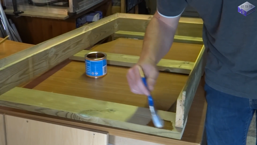
 While the frame of the solar  heater is made from external decking material, which is designed to withstand outdoor conditions, the plywood board needs to be coated with woodstain paint to prevent it from rotting when exposed to the elements.

Step 7: Seal and Finish The Heater

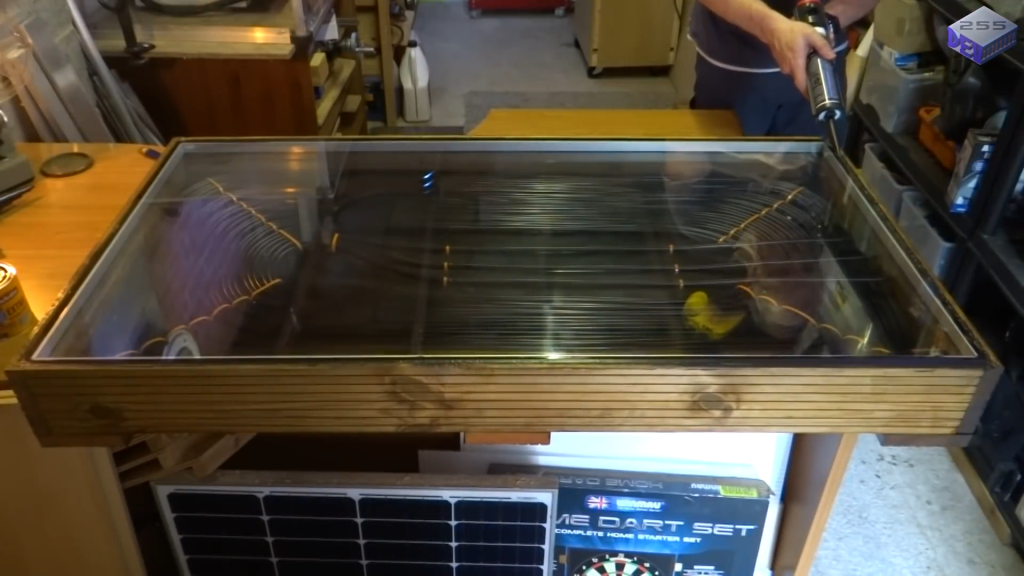
Carefully place the double-glazed glass sheet into the frame, ensuring it rests securely on the routed lip. Apply exterior silicon sealant around the edge of the glass to create a final waterproof seal.

Image Credits : Neil Devonshire – Dev255


OTHER DIY PROJECTS :

Loading...

To Order Some of My Books -- > ORDER FORM

Vision vs. Ambition in Ministry

Vision vs. Ambition in Ministry Vision is a God-given picture of what God desires to accomplish through us; ambition is a self-driven desir...